
Umbrella Arch
The umbrella arch is a temporary support system forming a structural umbrella from the insertion of an assortment of longitudinal support members installed from within the tunnel, above and around the crown of the tunnel face. The umbrella arch is often considered a pre-support technique as the support members are installed prior to the first pass of excavation. In this manner, the umbrella arch provides support to the ground ahead of and at the working face as well as the unsupported span immediately behind the working face, inside the tunnel. The latter is a primary distinguishing feature and benefit of the umbrella arch in comparison to other pre-support techniques, such as fiber-glass dowels (i.e. face bolting), which may be used in combination with the umbrella arch.
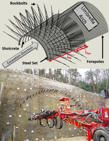
The longitudinal support members, extending ahead of the excavation face and composing the umbrella arch, can be broken down into three main support elements categories:
- Forepoles: element length greater than the height of the excavation, installed at shallow angles to the tunnel axis (e.g. 15m long steel pipe installed at 5 degrees);
- Spiles: element length smaller than the height of the excavation, primarily installed to control structural driven failure (e.g. rebar); and,
- Grouting elements
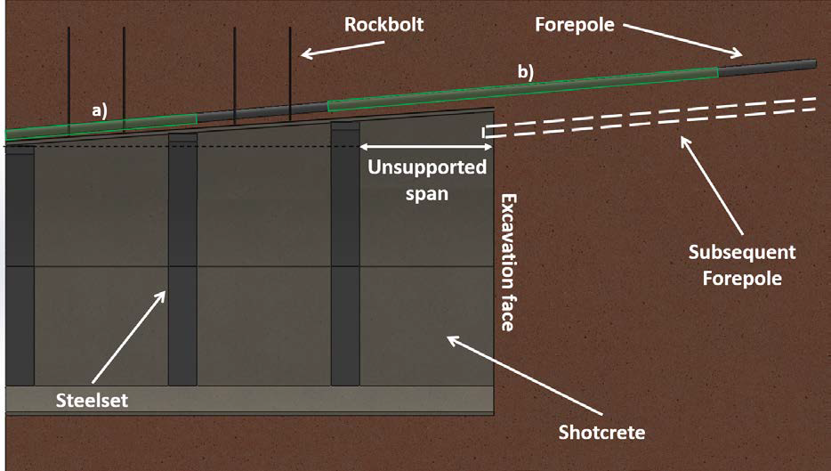
Forepole Support
Forepoles are passive support elements activated by movements of the ground mass. Their primary support contribution involves the longitudinal transfer of load away from the unsupported span. This is accomplished through bending of the forepole element (often steel pipe), which will be founded on the stiff steelset / concrete lining at two ends (refer to figure a.) or the steelset / concrete lining and ground ahead of the excavation face (refer to figure b.) depending on the construction stage. In this regard, the forepole acts as a multi-span beam to provide confinement to the unsupported span during construction . However, when initially installed the forepole will subjected to load in a cantilever fashion, as a 1-3m “free length” will exist until the steelset / concrete lining is able to be installed. Furthermore, depending on forepole / grout / ground interaction, axial loading of the forepole may be expected as a result of the stiff element resisting ground movements ahead of the excavation towards the tunnel. Respectively, the ground properties and strength and stiffness of the concrete lining / steelset will play a major role in the support contribution of the forepole elements.
Sources: Improving Ground Support Design with Distributed Strain Monitoring (Forbes B., Vlachopoulos N., & Diederichs M.S.)
Videos;