
Third Rail
A third rail is a method of providing electric power to a railway train, through a continuous rigid conductor placed alongside or between the rails of a railway track. It is used typically in a mass transit or rapid transit system, which has alignments in its own corridors, fully or almost fully segregated from the outside environment. In most cases, third rail systems supply direct current electricity.
The third-rail system of electrification is unrelated to the third rail used in dual-gauge railways.
Third rail systems are a means of providing electric traction power to railway trains, and they use an additional rail (called a “conductor rail”) for the purpose. On most systems, the conductor rail is placed on the sleeper ends outside the running rails, but in some cases a central conductor rail is used. The conductor rail is supported on ceramic insulators or insulated brackets, typically at intervals of 10 feet (3 metres) or so.
The trains have metal contact blocks called “shoes” which make contact with the conductor rail. The traction current is returned to the generating station through the running rails. The conductor rail is usually made of high conductivity steel, and the running rails have to be electrically connected using wire bonds or other devices, to minimize resistance in the electric circuit.
The conductor rails have to be interrupted at level crossings and at crossovers, and ramps are provided at the ends of the sections to give a smooth transition to the train shoes.
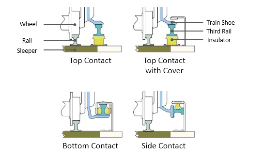
There is considerable diversity about the contact position between the train and the rail; some of the earliest systems used top contact, but developments used side or bottom contact, which enabled the conductor rail to be covered, protecting track workers from accidental contact and protecting the conductor rail from snow and leaf fall.
Benefits and disadvantages of third-rail systems
Electric traction systems (where electric power is generated at a remote power station and transmitted to the trains) are considerably more cost-effective than diesel or steam units, where the power unit is carried on the train. This advantage is especially marked in urban and rapid transit systems with a high traffic density.
So far as first cost is concerned, third-rail systems are relatively cheap to install, compared to overhead wire contact systems, as no structures for carrying the overhead contact wires are required, and there is no need to reconstruct overbridges to provide clearances. There is much less visual intrusion on the environment.
However as third rail systems present the hazard of electric shock, higher system voltages (above 1500 v) are not considered safe. Very high currents are therefore used, resulting in considerable power loss in the system, and requiring relatively closely spaced feed points (sub-stations).
The presence of an electrified rail also makes it extremely dangerous for a person to fall into the tracks. This, however, can be avoided using platform screen doors or the risk minimized by ensuring that the conductor rail is on the side of the track away from the platform.
Furthermore, third rail systems must either be fully grade-separated, or, if they operate at-grade, they must implement some kind of mechanism to effectively stop pedestrians from walking onto the tracks at grade crossings.
Third rail systems using top contact are prone to accumulations of snow, and ice formed from refrozen snow, and this can interrupt operations. Some systems operate dedicated de-icing trains to deposit an oily fluid on the conductor rail to prevent the build-up.
Because of the gaps in the conductor rail (at level crossings and crossovers) it is possible for a train to stop in a position where all of its shoes are in gaps, so that no traction power is available. The train is said to be “gapped”. In these circumstances a following train is brought up behind the stranded train to push it on to the conductor rail or a jumper cable is used to supply enough power to the train to get one of its contact shoes back on the third rail. On some systems this prevents the running of very short trains (which have fewer shoes).
Technical aspects
The third rail is usually located outside the two running rails, but occasionally between them. The electricity is transmitted to the train by means of a sliding shoe, which is held in contact with the rail. On many systems an insulating cover is provided above the third rail to protect employees working near the track; sometimes the shoe is designed to contact the side (called side running) or bottom (called bottom running) of the third rail, allowing the protective cover to be mounted directly to its top surface. When the shoe slides on top, it is referred to as top running. When the shoe slides on the bottom it is not affected by the build-up of snow or leaves.
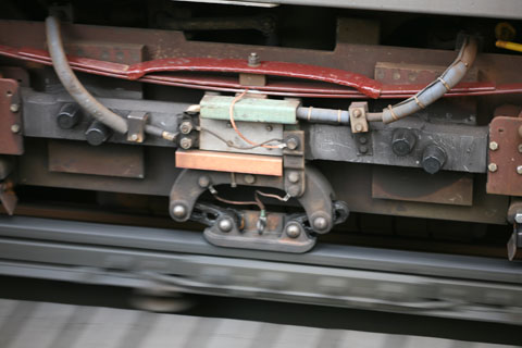
There are several ways of attaching the stainless steel to the aluminium. The oldest is a co-extruded method, where the stainless steel is extruded with the aluminium. This method has suffered, in isolated cases, from de-lamination (where the stainless steel separates from the aluminium); this is said to have been eliminated in the latest co-extruded rails. A second method is an aluminium core, upon which two stainless steel sections are fitted as a cap and linear welded along the centre line of the rail. Because aluminium has a higher coefficient of thermal expansion than steel, the aluminium and steel must be positively locked to provide a good current collection interface. A third method rivets aluminum bus strips to the web of the steel rail. The photo below-right depicts such a rail.
Technical advances
The introduction of supercapacitors has the potential to lower the cost for trains running on third rail and overhead wires. Kinetic energy generated while braking is stored in supercapacitors on board the vehicle. This energy is then used when accelerating. This allows the supercapacitors to reduce current draw through the electrical pickup during acceleration, putting less stress on the electrical grid. Claimed peak energy reduction is around 30%.
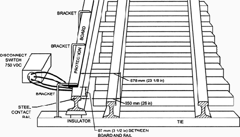
- Steel Contact Rail
Steel contact rail is the rail that carries power for electric rail cars through the tunnel and is placed parallel to the other two standard rails. - Contact Rail Insulators
Contact rail insulators are made either of porcelain or fiberglass and are to be installed at each supporting bracket location. - Protection Board
Protection boards are placed above the steel contact rail to “protect” personnel from making direct contact with this rail. These boards are typically made of fiberglass or timber. - Protection Board Brackets
Protection board brackets are mounted on either timber ties or concrete ties/base and are used to support the protection board at a distance above the steel contact rail. - Third Rail Insulated Anchor Arms
Third rail insulated anchor arms are located at the midpoint of each long section, with a maximum length for any section limited to 1.6 km (1 mile).
Sources: wikipedia.org, railway-technical.com and fhwa.dot.gov