
Submerged Floating Tunnel
Tunnels in water are by no means new in civil engineering. Since about 1900, more than 100 immersed tunnels have been constructed. Bridges are the most common structures used for crossing water bodies. In some cases immersed tunnels also used which run beneath the sea or river bed. But when the bed is too rocky , too deep or too undulating submerged floating tunnels are used .
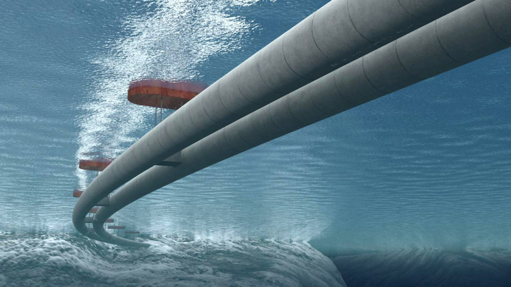
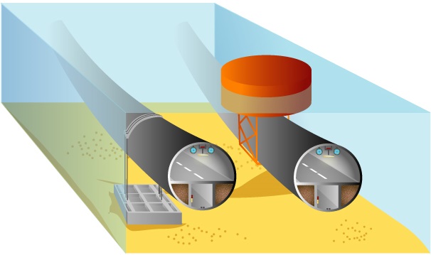
The Submerged Floating Tunnel (SFT) concept was first conceived at the beginning of the century, but no actual project was undertaken until recently. As the needs of society for regional growth and the protection of the environment have assumed increased importance, in this wider context the submerged floating tunnel offers new opportunities. The submerged floating tunnel is an innovative concept for crossing waterways, utilizing the law of buoyancy to support the structure at a moderate and convenient depth .The Submerged floating Tunnel is a tube like structure made of Steel and Concrete utilizing the law of buoyancy .It supported on columns or held in place by tethers attached to the sea floor or by pontoons floating on the surface. The Submerged floating tunnel utilizes lakes and waterways to carry traffic under water and on to the other side, where it can be conveniently linked to the rural network or to the underground infrastructure of modern cities.
Reason for Choosing Floating Tunnel
Floating tunnel is the totally new concept and never used before even for very small length. It can be observed that the depth of bed varies from place to place on a great extent. The maximum depth is up to 8 km. also at certain sections. The average depth is 3.3 km. The two alternatives are available for constructions are bridge above water level or tunnel below ground level. Since the depth is up to 8 km it is impossible to construct concrete columns of such height for a bridge. And also the pressure below 8km from sea surface is nearly about 500 times than atmospheric pressure so one cannot survive in such a high pressure zone. So the immersed tunnels also cannot be used. Therefore, floating tunnel is finalised which is at a depth 30m from the sea level, where there is no problem of high pressure. This is sufficient for any big ship to pass over it without any obstruction.
Basic Principle of SFT
SFT is a buoyant structure which moves in water. The relation between buoyancy and self weight is very important, since it controls the static behaviour f the tunnel and to some extend, also the response to dynamic forces. Minimum internal dimension often result in a near optimum design. There are two ways in which SFT can be floated. That is positive and negative buoyancy.
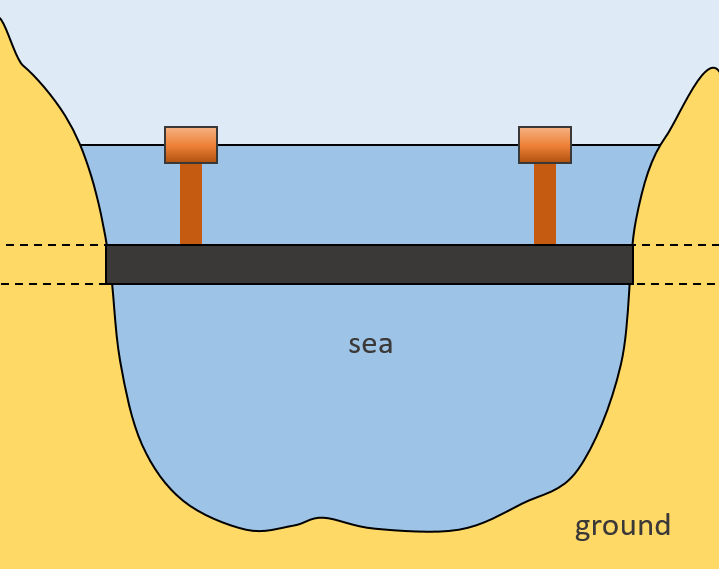
Positive buoyancy: In this the SFT is fixed in position by anchoring either by means of tension legs to the bottom or by means of pontoons on the surface. Here SFT is mainly 30 metres below the water surface.
Negative buoyancy: Here the foundations would be piers or columns to the sea or lake. This method is limited to 100 meters water depth.
SFT is subjected to all environmental actions typical in the water environment: wave ,current , vibration of water level, earthquake, corrosion, ice and marine growth. It should be designed to with stand all actions, operational and accidental loads, with enough strength and stiffness. Transverse stiffness is provided by bottom anchoring.
Construction
The concept of submerged floating tunnels is based on well-known technology applied to floating bridges and offshore structures, but the construction is mostly similar to that of immersed tunnels: One way is to build the tube in sections in a dry dock; then float these to the construction site and sink them into place, while sealed; and, when the sections are fixed to each other, the seals are broken. Another possibility is to build the sections unsealed, and after welding them together, pump the water out. The ballast used is calculated so that the structure has approximate hydrostatic equilibrium (that is, the tunnel is roughly the same overall density as water), whereas immersed tube tunnels are ballasted more to weight them down to the sea bed. This, of course, means that a submerged floating tunnel must be anchored to the ground or to the water surface to keep it in place (which of these depends on which side of the equilibrium point the tunnel is).
Diffirent Concepts for Submerged Floating Tunnels
Design Principle and Process of SFT Tube
SFT tube provides space for traffic and buoyancy for carrying different dead and live loads. The design of SFT tube relates to oneself safety and applicability. The design load, buoyancy to weight ratio, flow resistance performance, durable performance and other factors are considered comprehensively during the tube design process. By alternatives comparison from technique, economy and environmental protection, the optimal plan should extremely utilize the space to satisfy the traffic headroom and meet the demand of ventilation and escape according to the requirements of safety applicability, reliable quality, economical rationality and advanced technology.
The principles of tube design are as follows:
• The buoyancy to weight ratio is less than 1.0, related researches show that the ratio should be between 0.5 an0.8.
• Tube should meet the demand of strength, stiffness and stability during construction and operation stages.
• The variation of surface curvature should be gentle to resist the hydrodynamic. Meet the standard for classification of seismic protection of buildings.
Structural Components of SFT
Submerged floating tunnel consists of many structural components. These components should provide strength and stiffness against the various forces acting under the water surface.
The three basic structural components are:
• Tube
• Anchoring
• Shore connections
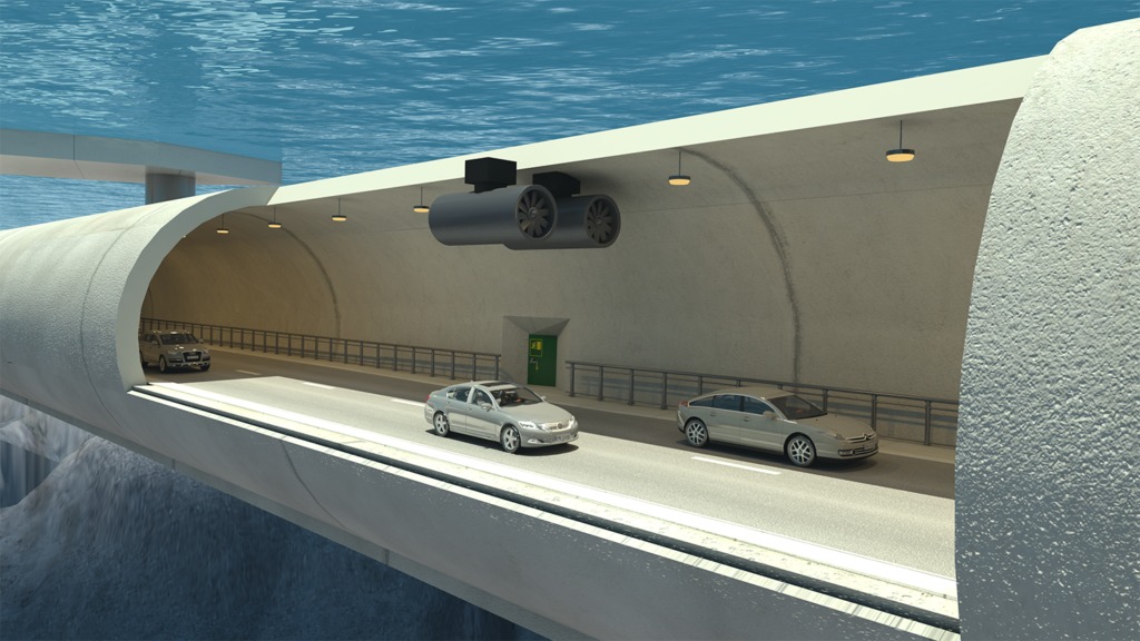
- Tube: It should accommodate the traffic lanes and the equipment. External shape can be circular , elliptical or polygonal. It may be constructed of steel or concrete. Corrosion protection is the main issue. Tube is composed of elements of length varying from one hundred meters to half a kilometre.
- Anchoring:
- SFT with pontoons
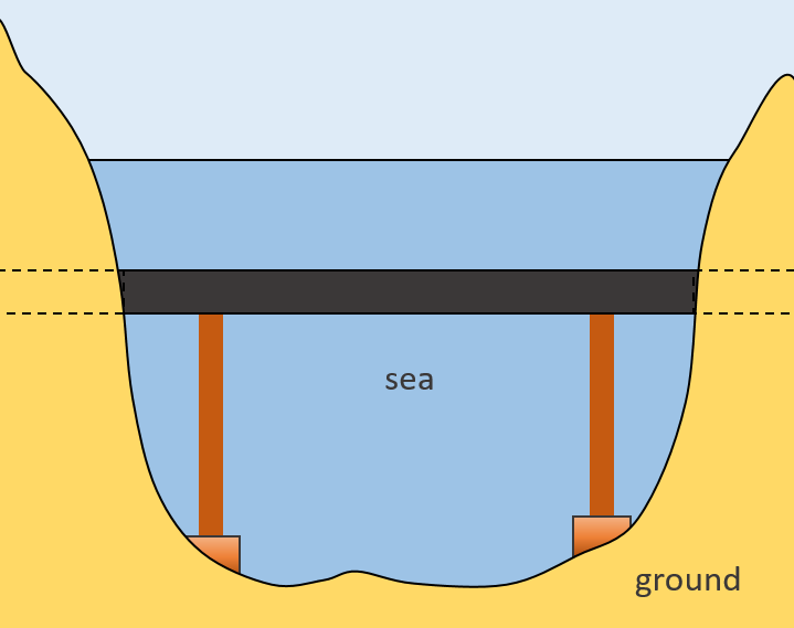
- SFT supported on columns
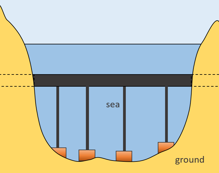
- SFT with tethers to the bottom
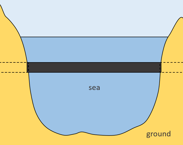
- SFT unanchored
SFT with pontoons: It is independent of water depth, the system is sensitive to wind, waves, currents and possible ships collision. Design should be such that if one pontoon is lost, then also the structure will survive.
SFT supported on columns: It is an “underwater bridge” with foundations on the bottom, in principle the columns are in compression but they may also be a tension type alternative. Water depth will play an important role in this case and a few hundred meters depth is considered a limit at the present time. However, much deeper foundations are at present under investigation.
SFT with tethers to the bottom : It is based on tethers being in tension in all future situations, no slack in these tethers may be accepted in any future load cases. The present practical depths for this type of crossing may be several hundred meters, whether the tethers are vertical or a combination of vertical and inclined.
SFT unanchored: It is interesting as it has no anchoring at all except at landfalls and is then independent of depth. There is obviously a limit to the length but only further development will answer this. Perhaps an alternative for light traffic should be designed, possibly a 100 or 200 meter long.
Connection:
The connections of the tube to the shore require appropriate interface elements to couple the flexible water tube with the much more rigid tunnel bored in the ground. This joint should be able to restrain tube movements, without any unsustainable increase in stresses. On the other hand , the joints must be water tight to be able to prevent entry of water. Additional care in shore connections is required, especially in seismic areas , due to the risk of submarine landslides
Structural design of SFT tube:
SFT tube keeps balance under the action of buoyancy and cable tension bears vehicle load, wave-current load, temperature load and so on. In the system transformation during prefabrication, floating, installation and operation, the stress of tube is complex, so the tube design should carry on longitudinal and transverse analysis under these working conditions.
SFT tube load is divides into permanent load, variable load and accidental load. The permanent includes structure weight, buoyancy, hydrostatic pressure, concrete shrinkage etc.
The variable load includes vehicle load, water head load, wave-current load, temperate load, construction load etc. The accidental load includes seismic, sunken ship load, blast load, leakage etc.
SFT tube is designed under ultimate limit state and serviceability limit state just as traditional hydraulic structure design [1], moreover, the stress and displacement should be analyzed and checked under progressive damage Limit state and fatigue limit state based on structural reliability theory.
Tube joint design
Joint design of SFT tube should conform to four principles:
- Not seepage in construction and operation stage, reliable water tightness and durability. Concise design, stressing definite and working independently.
- Transferring construction load effectively in construction stage and convenient construction.
- Transferring stress and deformation effectively in construction stage, fine seismic performance.
- There are two ways of tube joint based on stiffness and deformation: rigid joint and flexible joint.
Waterproofing and corrosion protection design of SFT tube
Tube ventilation design is an important link of SFT design, and quality of ventilation scheme and operation effect has direct relation to engineering cost, operation environment, disaster-relieving function and operation benefit. The aim of tube ventilation is to guarantee allowable concentration of harmful gas represented by carbon monoxide, provide healthy environment and suitable visibility for people and vehicle in tunnel, and control pervasion of smog and heat for evacuation and extinguishment when fire occurs.
Tube ventilation should accord with following requirements
- Design wind speed of one-way traffic tunnel is not more than 10m/s; design wind speed of two-way traffic tunnel is not more than 8m/s.
- Noise produced by ventilation fan and exhaust emission meet the environment protection guidance.
- Ventilation type is stable when the transportation condition changes or fire occurs. Downstream direction of operation ventilation is stable.
Proposals
A submerged floating tunnel has never been built (as of 2016), but several proposals have been presented by different entities.
- English Channel, United Kingdom.
- Strait of Messina, Italy.
- Høgsfjorden, Norway.
- Transatlantic tunnel (between North America and Europe) Atlantic Ocean.
- Funka Bay, Japan.
- Lake Washington, Seattle, United States.
- Vancouver Island, Canada.
- Lugano Lake, Switzerland.
Sources: engineeringcivil.com, wikipedia.com
Videos: