
Stray DC Current
The running rails in a DC electrified traction system are one of the main sources of electromagnetic disturbance to internal and external metallic structures and installations, such as civil works (viaducts and tunnels), pipelines and cables. The main electrical role of the running rails is to form the current return circuit, as well as form part of the signalling circuit for controlling the train movement. However, due to the imperfect insulation of the return circuit versus earth, the currents flowing in the running rails may leak to ground, flow in the soil and couple unto nearby bare or imperfectly insulated buried metallic structures, which offer low electrical resistance paths to the current. Where stray currents leave the metallic structures, corrosion and damage may occur, as well as overheating, arcing and fire; interference on signalling and communication systems with a low level of immunity, thus endangering people and equipment both inside and outside the railway or the trains.
The design objective to limit the intensity of the current which leaks to ground is based on the requirement to force the return current flow back to the traction power substation (TPS, dc supply) through its intended return path, i.e., the running rails. When a fourth rail is not employed as a dedicated conductor for the return current, adequate insulation of the running rails from earth and, additionally, a low running rail resistance (i.e., low longitudinal resistance of the return circuit) are required. In essence, the stray current depends on the value of the conductance per unit length of the running rails. The 1999 edition of standard EN 50122-2 recommends values for the onductance per unit length for areas where an effective risk of significant stray currents exists. These values can be achieved by means of provisions adopted during the design stage, such as clean ballast, insulated sleepers, adequate clearance between running rails and ballast, effective water drainage, running rails embedded in an insulating layer, and interposition of insulating layers between the tracks and the supported structure. This approach has been revised in the new version of the standard (edition 2010), where a maximum average value per unit length of 2.5 mA/m for the stray current of a single track line is introduced as a practical value. The stray current permissible limit specified in is based on practical experience gained from operational dc electrified railways, and is shown to represent a negligible risk of corrosion over a period of 25 years.
As it is impractical to measure the stray currents directly, the conductance and potential of the running rails against earth are assessed; moreover, the standard also dictates values for the conductance per-unitlength and for the average rail potential (over a period of 24 hours or multiples), that must not be exceeded. In case these requirements are not satisfied, further investigations are necessary. In any case, when provisions such as spacing of the substations, design of the civil structures and cross bonding of the running rails are not sufficient to minimize the stray current effects, a stray current collection mat may be considered. Voltage limiting devices (VLD) can also be provided as a protective provision to prevent impermissible voltages.
Stray Current Induced Corrosion
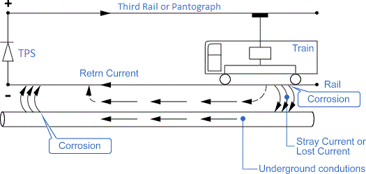
When the return current flowing in the running rails towards a TPS finds a low resistance alternative route to its intended path, such as a naked or not perfectly insulated metallic structure buried in soil or in concrete (e.g., pipelines, tanks, reinforcing bars, cables), it may leak to ground or concrete and flow in the metallic structure, which acts as the victim of interference. The magnitude of the leakage depends on the voltage drop in the rail (as a function of the current flowing in the rails and the resistance of the rails) and the resistance of the rails in relation to the ground. Each electric discontinuity of rail circuits increases the leakage of stray currents (even up to 50% of the return currents) and their instantaneous intensity in the ground can reach hundreds of amperes.
Traction stray currents are dynamic in character: their intensity and flow direction continuously change, depending on the traction load and location of electric locomotives in relation to the TPS. Dynamic potential changes of under ground structures and their random periods of anodic (corrosion) and cathodic (lack of corrosion) polarization are a consequence of this. The soil surrounding buried structures, as well as concrete, is the electrolyte. For the case of stray current released by a dc traction system, the electric interference results in a cathodic reaction of oxygen reduction where the current enters the metallic structure and in an anodic reaction of metal dissolution where the current leaves the metallic structure. In the anodic points the corrosion attack is localised and generally starts with the formation of pits, which may then increase in number and size. The situation of electric interference generated by a dc railway on a metallic structure is illustrated in following figure.
Stray Current Collection System
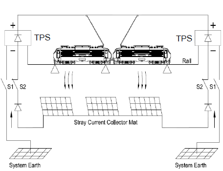
A stray current collection system is a means to pick up the stray current that leaks from the running rails, in order to provide a low resistance path for the stray current itself, thus avoiding possible interference with third-party infrastructures. The upper layer of reinforcing bars in the concrete track bed of a traction system may be used for this purpose. Such a stray current collection mat has then a twofold function: it works as a structural support and as a conductive path for the stray current. The rebars are welded together into sections and the sections are connected together in a way to provide a low resistance continuous path for the collected stray current. The stray current design philosophy is based on the requirement to minimise the initial generation of stray current, control the flow of the leakage current and ensure adequate electrical separation between the stray collection system and railway and external structures. This is achieved through the following design activities:
- Minimising the potential for stray current through an effective Traction Power Substation (TPS) design and rail return current circuit;
- Minimising the leakage of current through the provision of high insulation between rail and the structure.
- Controlling the distribution of stray current by the construction and maintenance of stray current collection systems, to provide an efficient low resistance preferential path for current collection and return;
- Maintaining either electrical separation between the collection system and other conductive parts of the structure
(tunnels and Cut and Cover) or the total inclusion of all potential paths to earth within the system; and - Minimising the longitudinal electrical conductivity of supporting structures.
The overall stray current collection system implemented is shown schematically in following figure.
Source: https://www.researchgate.net/publication/261132423 Mitigation of electromagnetic interference generated by stray current from a dc rail tractionsystem.