
Simulation Software Categories for Tunnel Ventilation Systems
Software applications used for the design of tunnel ventilation systems fall into two general categories: onedimensional onedimensional, also known as network analysis, and two or three-dimensional CFD. In network analysis, the properties of air (velocity, pressure, temperature) are considered to be homogeneous across a transverse tunnel section taken at any location in the system. This is an acceptable simplification when considering systems in which the airflows are primarily longitudinal such as a tunnel). Consideration of more complex three-dimensional spaces such as underground stations often requires the use of CFD techniques, particularly when modeling fires.
1- One-Dimensional Analyses
One-dimensional analysis is used extensively in tunnel ventilation design. The software tools allow integrated modeling of the aerodynamic, thermodynamic, and fire scenarios associated with subsurface airways. An example is the freely-distributed Subway Environment Simulation (SES) Computer Program, developed by the United States Department of Transportation, Federal Transit Administration. This software allows dynamic simulation of trains (piston effect), and provides output for air velocity, temperature, and humidity. The program also computes cooling and heating capacities required to satisfy environmental criteria, and the long-term effect of the system on the temperature of the surrounding strata.
The ventilation system of fans, tunnels, stations and dampers are modeled using Subway Environmental Simulation (SES). Input to the model includes details of plant, civil/builder details and the loads to be controlled by the ventilation system(to be refined). Output from the model includes air volume flow rates, pressure profiles and changes in air temperature caused by the heat output of the loads to be controlled.
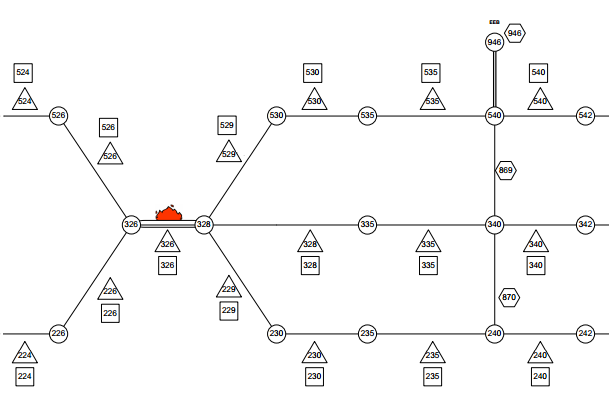
- SES node diagram
Other computational sequences are incorporated to model the effects of a fire. These effects include:
– Throttling efect on the ventilating airflow due to rapid expansion of the air flowing past the fire.
– Viscous pressure losses due to the fire.
– Increase of wall surface temperature downstream of the fire and the impact that this has on the airflow.
– Heat transfer processes associated with fire.
– The effect of the elevate air temperature on the performance of downstream fans.
2- CFD and Evacuation Software (3-Dimensional)
CFD techniques are increasingly used to model fires. They allow for a more detailed representation of the behavior of a fire and the environment in which it occurs. Unlike network analysis, where it may be necessary to compare an achieved airflow velocity against an independently calculated critical velocity to determine if back-layering will occur, CFD analysis is able to directly predict movement of hot smoke and fire gases based upon first principles.
Figures 1 and 2 show visibility plots for a fire simulation conducted for a typical modern subway station. The outline of the station can be seen in Figure 1, with visibility contours plotted for a vertical slice taken through the fire and along the length of the station. Figure 2 shows visibility at head height above the platform level of the station, as seen in plan view. The different plots represent different simulation and evacuation times.
The coupling of CFD fire modeling with virtual reality software and evacuation simulators allows visualization of the processes taking place during these complex events. This relatively new level of visualization, in addition to being a valuable design tool, is helpful in the development of emergency procedures and can be used to improve operator training.
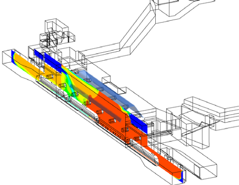
- Figure 1. Visibility contour plot for fire in a subway station: vertical slice along the station.
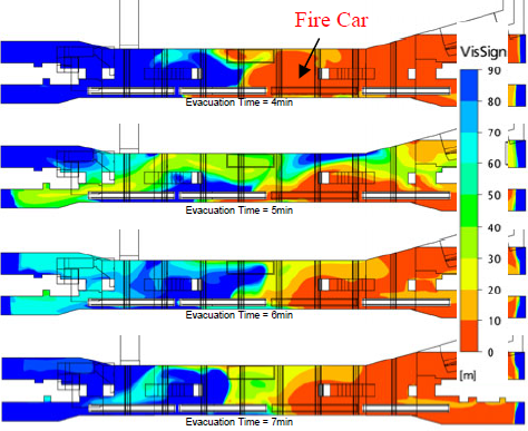
- Figure 2. Visibility contour plot: horizontal slices for different evacuation times.
Sources; smenet.org, tdt-e.com
Videos;