
Rigid Catenary (or Overhead Contact System)
 The rigid catenary is an Overhead Contact System (OCS) that can replace, with many advantages, the contact wire with sustentation wire, the third rail or the suspended bimetallic T-rail.
It is formed by an aluminium alloy profile, which accommodates the copper contact wire, with a great cross section for the current that allows operative OCS voltages from 750 to 1.500 V, without any feeding supply. It has been also installed in lines with a feeding supply of 25 KV.
Rigid catenary system is a new power supply mode of electrification railway, comparing with the traditional flexible catenary system, it has below advantages.
1- more capability of current carrying
With large cross section current bar profile clamping contact wire, current bar profile and contact wire clamped in the draw-back collet current bar profile can permit high level current passing. Further more it can effectively reduce the radiation problem which caused by high level current.
2- No risk of breaking-off, more security
As there is no traction stress, it allows more contact wire wear without risk of breaking-off in rigid catenary system, the only limitation is that the pantograph can not touch the current bar profile.
3- Easy operation and maintenance
As the contact wire allows more wear and its installation and replacing is easy in rigid catenary system, the maintenance cost is greatly reduced. Periodical control of the current bar profile connectors tightening and cleaning up of the isolators are the only maintenance operations to be carried out
4- less tunnel clearance, less construction cost
Rigid catenary system reduces great tunnel clearance against standard catenary system, so the construction cost is greatly reduced.
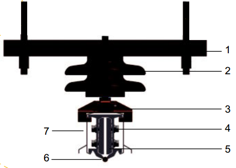
Typical Installation Structure
1-Supports 2-Insulator 3-Steady Clamp 4- Current Bar Profile 5- Connect Joint 6- Contact Wire 7- Protecting Plastic Cover
Components of Rigid Catenary
1- Conductor profile
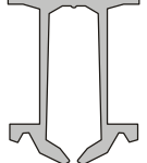 It is manufactured by extrusion from a 6063 aluminium alloy and heat-treated, in bars of 10 or 12 metres length and with 8 holes in each end to allow their joint with bolted joint plates. The profile has a gap at its bottom for placing the contact wire using a special device. The height of the profile is 110 millimetres and its cross section is 2.220 square millimetres (Fig. 1).
Fig. 1
2- Joint plate
It is manufactured with the same alloy that the conductor profiles and it is assembled using 8 stainless steel AISI-304 bolts and washers. The joint plate is designed in such a manner that, when bolts are screwed, it couples to the internal form of the profile, self centring the joint and allowing a perfect alignment between the profiles.
3- Contact wire
It is designed with the suitable cross section that allows a perfect fit with the conductor profile. Its cross section is 107 square millimetres accepting also up to 152 square millimetres. The pressure between the aluminium conductor profile and the contact wire is 15 KN/m, which allows a perfect electrical contact.
4- Support insulator
It is manufactured with synthetic material reinforced with glass fibre and stainless steel (AISI-304) fittings. It is mounted at the top part of the profile, working as its support. It is provided with sliding material, which allow free longitudinal movement of the catenary, without any additional stress for the insulator.
It is resistant to chemical products such as mineral oils, alcohols, hydrocarbons, benzenes used in railways and also to salt solutions from ice breaks-up. It has very good mechanical aging properties outdoor even at temperatures ranging from -50 oC up to + 80 oC.
5- Current feeder connection
It is performed by an aluminium clamp with stainless steel (AISI-304) fittings which allows the connection between the feeder and the catenary, or the electrical connection between two different profiles by means of a flexible wire. When copper wire is used, a bimetallic terminal must be used.
6- Protection cover
It is manufactured by extrusion of PVC, in 6 metres length and fitted to the aluminium profile in order to protect it against dust and humidity. It is often used at the entrance of tunnels or high humidity areas. It is also used in stations, where it improves the safety and the aesthetical appearance of the installation.
7- Spring profile
It is manufactured with the same alloy that the conductor profiles. It is used to link the standard OCS with the rigid catenary, taking up the different mechanical rigidity between them, and to avoid that the contact wire breaks due to mechanical stress.
A common way to make the transition between both contact systems that offers good results, avoiding using a spring profile, is to use air sections assembly (Fig. 2). To do that, the standard wire contact must be fixed to a hanging wall, while the rigid catenary continues with its own supports.
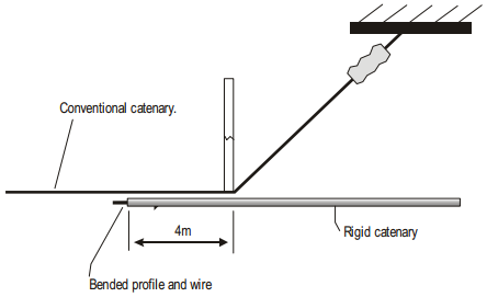
Fig. 2
Aluminium/Copper Corrosion
To prevent the possible galvanic corrosion between aluminium and copper, the following procedure is carried out:
Each bar has ventilation holes in the lower part to avoid inside condensation, eliminating the necessary electrolyte for the transport of ions.
The contact wire must be lubricated during its installation, using a special grease that both protects against corrosion and facilitates the flow of the current between the contact and the conductor profile.
Stress Produce By Thermal Expabsion Of The Profile
The longitudinal expansion coefficient of aluminium is 24.10-6, it means that length variations of catenary may be significant.
For a difference of 40 oC, due to electrical currents and environmental temperature, the variation of the profile length would be about 100 millimetres for every 100 metres.
The slides of the support insulators allow the free movement of the profile without any tensile stress in it.
Nowadays, all the expanding joints that can be found in the market are expensive and not so much efficient. Experience has demonstrated that the interruption of the catenary every 450-500 metres, assuring the continuity as show in Fig. 3, is the most efficient system to avoid the stress produced by the thermal expansion.
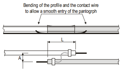
L and A dimensions depends on the speed and the pantograph width. The radius at both ends depends on the pantograph model.
Supports
The rigid catenary works as a continuous beam, therefore the current deflection is lower than on a single span for the same profile (Fig. 4).
The supports must be placed every 5 metres to reach a maximum deflection lower than 1o which allow speeds up to 120 Km/h and occasionally 160 Km/h.
Also, experience has demonstrated that supports can be placed every 12 metres for speeds up to 90 Km/h.
Therefore, the distance between supports depends on the maximum speed requested by every railway administration. The alignment of the supports must be made with accurate devices, for example, by using a laser level. The difference between two consecutive supports must be lower than 1o .
For sections between 400 and 500 metres with important ramps and zones of high speed, it is necessary a fixed point in the middle of this section (Fig. 5).
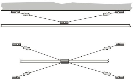
Fig. 5
It does no exist a standardized design for this mounting. It must be customized to the available gauges.
Advantages To Use Rigid Catenary
1- Using rigid catenary, the tunnels gauge may be reduced (Fig. 6). The required gap between the catenary and the roof is about 400 mm., although it would be possible to install it with a 300 mm gap.
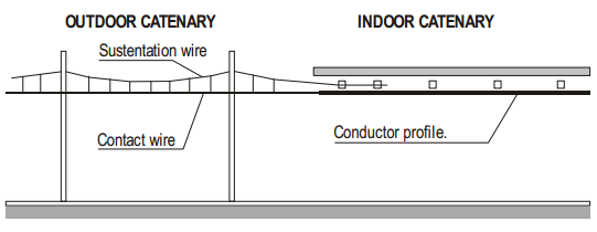
Fig. 6
2- Because there is no mechanical stress on the contact wire, a great wear is allowed (30%) providing that the pantograph does not come into contact with the aluminium profile.
The contact wire is usually mounted with a tensile stress of 10 KN, which reduces its mechanical strength. This fact, as well as the short circuits caused by the action of the pantograph, increase the risk of the contact wire break, engagement of the pantographs and its fall on the platforms, resulting in a great danger for the passengers. With rigid catenary, all these risks disappear.
3- The equivalent copper cross section may be 1500 mm2, which is about 5 times the usual in conventional overhead contact systems. It means that no additional feeders are usually required.
4- Also the maintenance costs is one of the advantages of this system. Because a great wear out or the contact wire is allowed, its replacement is not so frequent. On the other hand, the time required to carry out this operation is very much low and many times it is not necessary to replace the complete section, as in the usual contact wire, and only the affected sector will be repaired. This is to say, replacement of the rigid catenary contact wire is 10 times faster than with conventional one because the amount of bolts and screws to remove is lower.
The periodic control of the joint plates bolts tightening and the cleaning of the insulators are almost the only maintenance operations.
On the another way, the damages produced by short circuits or over loads can be repaired very fast, replacing a short stretch of the contact wire (1 or 2 metres), without any consequences in the current supply and allowing trains can be running again in a few minutes, due to that this operation can be made in about 15 minutes.
In the case of rupture of an insulator (Fig. 7), the defection at this point would allow trains run slowly.
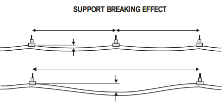
Fig.7
5- With the rigid catenary, the wear of the pantograph is lower than with the conventional contact wire. In order to allow an even wear of the pantograph, the conductor profiles may be bended during the mounting, with a radius greater than 100 metres only with a lateral pressure on the fittings (Fig. 8).
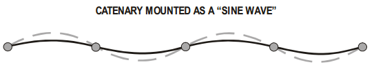
Fig.8
6- The rigid catenary follows the curves of switches and crossings perfectly, without any section insulator or fittings.
7- When the rail track is well maintained the trains may run up to 120 Km./h with a lower wear of the pantograph.
Earthing
Earthing of conductor profiles, as required for maintenance works, is made by fitting at the top of the profile an aluminium plate provided with an earthing connection bar that allows to fits the earthing conductor (Fig. 9).
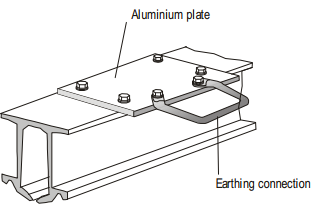
Fig. 9
To use this device is essential in air-sections and stations.
Contact Wire Assembly
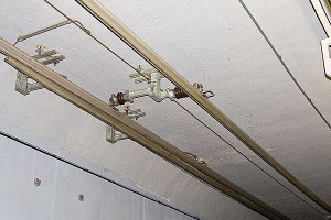
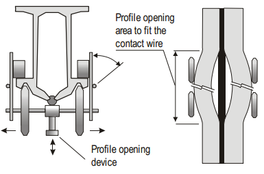
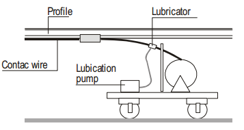
The aluminium profile may be placed and properly aligned by using the standard devices commonly used for mounting the conventional catenary because of the low weight of profiles (a bar of 12 m. is 73 Kg in weight), the contact wire must be fitted on it. This operation is made using a special device which is suspended of the profile and that allows to open the bottom part of the profile to place the wire contact (Fig. 10).
The contact wire drum and the lubricating device are placed on a railcar (Fig. 10 & 11). The wire mounting speed is about 2 Km/h.
Sources: klk.es, daqo.com