
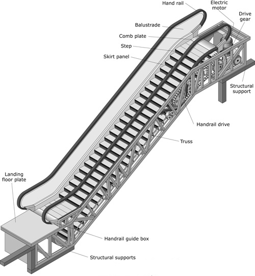
Heavy-Duty Escalator
Heavy-duty escalators are used in mass railway transit systems as rapid transit (metro), LRT.
A. Design Criteria
A.1. Operational requirements
- Hours of operation shall be considered as 24 hours per day, seven days per week.
- Direction of travel shall be considered as either direction, and unit shall be up-and-down reversible.
- Rated speed shall not exceed 100 feet per minute (FPM). The no-load-to-full-load speed shall not exceed 4 percent of the rated speed.
- Escalator components shall be designed based on the design loads, following applied duty cycle during operation:
- Three hours with 100 percent design load
- Six hours with 50 percent design load
- Fifteen hours with 25 percent design load
A.2. Environmental requirements
Escalators shall be capable of operating with fully specified performance capability while exposed to the following climatic and environmental conditions:
- Interior installations: Escalators shall be designed to operate in a temperature range of 5 to 120 ºF, dry bulb, and all conditions of relative humidity while exposed to airborne dust and debris.
- Exterior installations: Escalators shall be designed to operate while exposed to the natural elements of weather, including sunlight, rain, slush, snow and ice; all conditions of relative humidity while exposed to salt, deicing chemicals, airborne dust, and debris, and corrosive elements; and in a dry-bulb temperature range of -10 to 105 ºF.
A.3. Fire protection
- No wood or wood products shall be used in escalators.
- LSHF (low-smoke, halogen free) wiring shall be used where commercially available throughout the escalator installation.
- PVC may not be used in the escalator installation.
B. Products
B.1. General
- Inclination: Not to exceed 30 degrees. (Consider 27-degree escalators for very high rise escalators, generally over 10 m.)
- Nominal step width: 1,000 mm (40 in.) or 800 mm (32 in.).
- Speed: Not to exceed 100 FPM.
- Flat steps: Three minimum for less than 10 m (32 ft, 10 in.) rise; four minimum for greater than 10 m (32 ft, 10 in.) rise.
- Maintenance speed: No greater than 25 percent of rated speed.
- Upper track radius: Less than 10 m (32 ft, 10 in.) rise: 2.6 m (8 ft, 6 in.). Greater than 10 m (32 ft, 10 in.) rise: Consider larger radius.
- Lower track radius: 2 m (6 ft, 6.75 in.).
- Static brake load (load per step on the total number of exposed steps on the incline):
- 1,000 mm step: 306 kg (674 lb)
- 800 mm step: 245 kg (540 lb)
- Dynamic brake load (load per step running in down direction on exposed steps on the incline):
- 1,000 mm step: 145 kg (320 lb)
- 800 mm step: 116 kg (256 lb)
- Motor duty load. With a minimum step load per step (on incline only) as follows:
- 1,000 mm step: 145 kg (320 lb)
- 800 mm step: 116 kg (256 lb)
- Step chain load. To be based on the step loads as follows:
- 1000 mm step: 145 kg (320 lb)
B.2. Controls and safety devices
Operating controls
- Escalators shall have key-operated switches, accessible at both upper and lower landings, located on the exterior deck above the newel base. Alternate locations may be used subject to approval by the owner.
- Each keyed switch shall be clearly and permanently labeled, including starting and direction selection.
- Interlocks shall be provided to bring the escalator to a smooth stop, in either direction of travel, before a change of direction may be made.
Safety devices
- Safety devices include but are not limited to those required by the edition of ASME A17.1 in effect
for this installation.
- A lockable stop switch or disconnect shall be provided in both pits of escalators.
- A switch shall prevent operation of the escalator if any part of the floor plate is not in place. This shall not be a manual reset device.
Balustrades, skirt panels and decking
- Panels shall be a minimum of 3 mm solid type 316 stainless steel and backing panels, where used, shall be noncombustible and are subject to owner approval.
- Panels shall be constructed, when practical, in equal lengths for interchangeability.
- Panels shall be attached to permit easy removal for inspection, lubrication and adjustment of safety devices.
- Panels shall be sized so that no more than two people are required to remove a panel, and without the aid of special handling equipment.
- Requirements for exposed panel fasteners (where used): Panels shall be fastened to their respective supports or mating portions with tamperproof flathead machine screws.
- When the framework to which panels are fastened is less than 0.25 in. thick, steel backup plates with a minimum 0.25 in. thickness shall be added. These plates shall have tapped holes or clearance holes where necessary.
- Decking shall be a minimum of 2 mm thick solid type 316 stainless steel, identical in finish to balustrade.
- Decking between escalators shall be designed to support a live load of 175 lb/ft2 without permanent deformation.
- Paneling, decking and other enclosures shall be supported on a steel frame.
B.3. Electrical equipment
Motors
- The driving motors shall be AC induction motors with starters. Voltage 480 VAC, three phase, frequency 60 Hz.
- The motors shall be totally enclosed with external cooling fins.
- The motor protection class shall be equivalent to IP55 insulation group F.
- Driving motors and motor switchgear shall provide a smooth start.
Controller
- The escalator control equipment shall contain diagnostic capabilities as required for the ease of complete maintenance. The diagnostic system shall be an integral part of the controller and provide user-friendly interaction between the service person and the controls. All such systems shall be free from decaying circuits that must be periodically reprogrammed by the manufacturer.
- Switchgear shall be mounted in NEMA 4X cabinets with strip heaters and labeled terminal strips.
- The main controller shall use a programmable logic controller (PLC) to control and monitor the status of the escalator. The PLC shall be designed to communicate over Ethernet or approved equal.
- The PLC racks shall provide space for two future single-slot modules.
- The PLC in the remote control panel shall also have hardware and firmware provisions to communicate with interactive operator interface (monitor).
- The PLC shall store the last 99 safety device faults, accessible via laptop connection, panel view or remote communications.
- A copy of all working programs on approved computer medium, as well as a printed program listing, shall be provided.
- The PLC shall have one dedicated serial port, which supports RS-232-C signals. It shall be accessible in ladder logic and provide support for point-to-point and slave SCADA communication protocol systems. Alternatively, it must be usable for programming purposes or for access to remote programmers via modems.
Main control switchgear
The main control switchgear of an escalator shall contain at least the following devices:
- Lockable main switch thermal and magnetic motor protection starter for up and down travel, hour counter, auxiliary contactors, phase failure device, phase sequence monitor and ground fault monitor.
- The controller cabinet shall contain a permanently mounted full-color view panel capable of providing fault and operating data.
- The indication shall be locked automatically. Reset shall be done by a separate switch installed in the controller. The emergency stop shall not be locked.
- All terminals shall have identification markings, and all cables shall be provided with cable markers.
- The controller shall be equipped a full-time regenerative variable frequency drive (VFD) capable of full-speed control for maintenance and future “sleep mode” operation.
- Electric power receptacles shall be furnished and installed in the upper and lower pits. Each receptacle shall be of the GFCI duplex type, waterproof, grounded, and rated for one 120 volts at 20 amperes. The receptacles in the pits shall be surface-mounted on the walls, not less than 30 in. from the floor.
- Relays shall be provided with visual indication that they are energized.
- Controllers in escalator pits shall have a flexible liquid tight connection of suitable length to permit removal for maintenance purposes.
- The controller shall be capable of operating the escalator in variable rated speed operation as per ASME A17.1-2010 requirement 6.1.4.1.1, regardless of the ASME A17.1 code in effect.
Optional
- The escalator shall be provided with the capability of running at any speed up to and including the indicated contract speed. The speed of the escalator shall be user selectable and shall be displayed on the HMI.
- Activation of sleep mode and setting of the sleep delay and sleep speed parameters shall be performed on the PLC’s LCD display. The LCD display’s main screen shall indicate if the escalator is in sleep mode operation and what the sleep delay and sleep speed parameters are.
Truss wiring and conduit
- Galvanized rigid pipe and/or liquid tight flexible metal conduit shall be used in the truss.
- In Class 2 circuits, SO cord may be used in lengths not to exceed 3 ft.
- Liquid tight flexible metal conduit must be CSA/UL approved.
B.4 Materials
Stainless steel
- Shapes and bars: ASTM A-276, type 304 or 316, A-554 for tubes.
- Plate, sheet and strip: ASTM A-240. Type 304 for interior installations and 316 for exterior installations.
Fasteners
- Fasteners shall be compatible with materials being fastened. Fasteners shall be furnished with selflocking nuts or retaining rings (spring washers, toothed disks).
- Fasteners shall be equal to or of greater corrosion resistance than the most corrosion resistant metals being fastened.
B.5 Finishes
- Stainless steel: No. 4 finish ASTM A-480.
- Aluminum castings and extrusions: Commercial mill finish.
- Galvanizing:
- Sheet steel: ASTM A446 or A526, as applicable. Coating designation G185.
- Other galvanizing: ASTM A123, ASTM A 153, ASTM A 385 or ASTM A 386, as applicable.
- Galvanizing touch-up: Zinc dust coating, MIL-P-21035 or MIL-P-26915.
- Paint and corrosion protection: Each escalator shall have the following minimum corrosion protection:
- After welding, the truss shall be hot dipped galvanized with a coating in accordance with ASTM A90. A 100 percent zinc thermal spray coating to ASNI/AWS C.18-93 is an acceptable alternative.
- Cast metal parts such as gear housings, chain sprockets and return station half circles shall be painted with a rust inhibitor primer coat after preparation by sandblasting.
- Steel parts that are not specified to be galvanized shall be painted as follows: Primer coat: 2 mil (dry film thickness) minimum thickness. Second finish coat: 2 mil (dry film thickness) minimum thickness.
- Bright or uncoated axles, shafts, etc., shall be protected by zinc chromate or chrome plating.
- Oil collector chutes and collection trays shall be fabricated of galvanized steel.
B.6 Mechanical equipment
B.6.1 Tracks
- Fabrication of tracks shall retain steps and running gear safely under load requirements and at the highest speed specified.
- Installer shall assemble and secure sections of track together for easy removal and replacement of defective sections. The system shall be adjustable, and connecting of the track sections by welding is not acceptable.
- Design of the mechanical components shall provide for easy installation and removal without the dismantling of parts of the structure.
- Tracks shall be properly supported on trusses to provide correct alignment and smooth transition to return stations. The rolling surface of the passenger side track shall be a minimum thickness of 3 mm.
- Return side track shall be a minimum thickness of 2 mm.
- The guiding system for the step chains and step wheels shall be of zinc plated or galvanized steel profiles with smooth and even running surfaces and with the joints cut diagonally to the running direction. The guide profiles shall not be welded together at the joints.
- A second, continuous guiding profile shall be provided above the step chain rollers so that the step chains are positively guided in the area of the escalator open to passengers.
B.6.2 Steps
- The entire step assembly shall treated with not less than one coat of zinc chromate primer or iron phosphate and one coat of powder-coated enamel for corrosion resistance.
- Steps and their various attachments shall permit removal of steps without disturbing balustrades.
- The design shall permit the running of the drive without steps for convenience in cleaning and inspection.
- Step rollers shall have polyurethane tires on hubs, sealed roller bearings, and a diameter of no less than 3 in. Step rollers shall not require any additional lubrication and must be rated for severe, heavyduty service. Step roller bearings shall have an L10 rating of 100,000 hours.
- Steps shall be constructed so as to be driven by step linkages to step or step rollers.
- Washers and nuts shall be provided as follows:
- Tap bolts: Lock washers.
- Through bolts: Lock nuts or owner-approved equal.
Rated loads
- In addition to the minimum requirements given in the codes, the installer shall design the steps for a minimum load of 320 lb (145 kg) per 40-in. step or 256 lb (116 kg) per 32-in. step with an ultimate strength safety factor of 8.
- The steps shall carry the load under maximum concentric and eccentric loading conditions without failure.
- Die-cast aluminum steps shall not have more than 0.3 percent copper content.
B.6.3 Step chain
- Chain shall be endless, roller-type step chains with one on each side of the step.
- Step chains shall be of heat-treated steel construction, supported at intervals by linkage wheels.
- A means to prevent steps from coming into physical contact with one another and to prevent chains from sagging or buckling shall be provided.
- A means to maintain constant distance between step axles shall be provided.
- An automatic tensioning device to maintain tension under load and to compensate for wear shall be provided. The device shall be located within the truss at the lower end.
- A means for individual fine adjustment of tension for each linkage shall be provided.
- Step chains shall be constructed to permit removal of segments as may be required for replacement purposes at a minimum of every six-axle section. Each escalator shall have at least two one-axle sections.
- Support wheels spaced to distribute load and to guide linkage throughout the run shall be provided. Rollers shall be constructed of polyurethane material, with a diameter sufficient to provide reliability, maintainability, smoothness of motion and to operate within the noise level requirements specified. The chain rollers shall have polyurethane tires, sealed bearings and diameters of not less than 4 in. They shall require no additional lubrication and be mounted outside chain link. The wheels, hubs and bearings shall have an L10 rating of 100,000 hours.
- Wheels shall be affixed to permit rapid replacement.
- Each pair of step chains shall be a matched set within manufacturing tolerances. Only precision, rollerfishplate chains of high-grade heat-treated steel shall be used as step chains. The pins, axles, bushing and rollers shall be hardened and ground.
- Step chain and chain pins shall have a surface pressure at engaging points that shall not exceed 30 N/mm2 (3,450 psi). This is to be based on the step loads as defined in the step chain load requirement in Section B.1.
- The safety factor shall be at least 6.
- A test certificate for the chain-breaking load shall be provided.
- A shielding device shall be provided to protect chain, track guides and rollers against water, dirt and debris.
B.6.4 Combplate assemblies
- Complete assemblies of wear-resisting, noncorrosive metal material with exposed anti-slip surfaces shall be fabricated.
- A separate switch for vertical and horizontal detection shall be provided.
- Combplate sections meeting the following requirements shall be provided:
- Shall be removable to permit ease of replacement.
- Shall be yellow in color for safety/demarcation.
- Provisions for lateral and vertical fine adjustments shall be provided so that cleats of step treads pass between combteeth with minimum clearances.
B.6.5 Floor plates
- Shall have type 316 stainless steel frames at floor openings, designed to be supported on truss heads.
- Shall be designed to cover entire area of upper and lower landings.
- Shall be reinforced, as necessary, to be rigid and able to withstand a live load of 250 lb/ft2 with zero permanent deformation.
- Shall be extruded or die-cast aluminum in a ribbed pattern transverse to the escalator axis. Ribs shall be designed to provide maximum traction, and will be finished in the same manner as the combplates.
- Shall have exposed portions constructed of material and finish to harmonize with steps and combplates.
B.6.6 Drive machinery
Select one:
- Motor and drive mechanism shall be mounted within the truss envelope at the upper end. Shafts shall be designed for ease of assembly or disassembly.
- Motor and drive mechanism shall be mounted outside the truss envelope in the upper head section. The drive shall be securely fastened to a bedplate and have chain guards provided around the drive chains. Shafts shall be designed for ease of assembly or disassembly.
Gear box requirements
- Gear bearings shall be rated with an ABMA L10 life of 200,000 hours and housed in an oil-tight, dust-proof case. The case shall provide a convenient method of draining the oil.
- Synthetic lubricants shall be used, subject to owner approval.
- Rotating parts shall be provided with a means for lubrication and retention of lubricants.
- Sealed bearings shall be used.
- Exposed, moving drive elements shall be protected by metal housings, which shall provide access for lubrication of components.
- A low-oil sensor shall be provided to prohibit starting of the escalator on automatic operation with low oil in the gearcase.
Other
- V-belt and tooth belt drives shall not be considered acceptable.
- Head shaft bearings shall be rated for ABMA L10, 200,000 hours.
B.6.7 Drip pans
- Galvanized, 3 mm steel, watertight drip pans for the entire length and width of trusses shall be provided. They shall also be sloped for proper drainage and collection of lubricants, as well as any moisture or water that may enter the escalator. They shall be constructed to prevent oil from leaking below the truss.
- Drip pans of sufficient size to collect and maintain, within truss areas, oil and grease drippings from step linkage and all forms of loose debris that maybe deposited from steps at turnaround points at the upper and lower portions of truss shall be provided. This system shall be separate from the water drain in order to prevent the discharge of lubricants into the drainage system.
- Access to drip pans at lower landings of escalators shall be provided for the purpose of cleaning drain catch basins.
B.6.8 Handrails
- Handrails shall receive their motion from the main escalator drive through direct gearing and drive shaft or drive chains, so that the handrail and steps operate at the same speed in each direction of travel. Driving and guiding wheels shall have a groove to accept the wedge on the underside of the handrail. The handrail shall have a V-shape wedge.
- A means to take up handrail slack using a tensioning device, where required, shall be located within escalators. In addition, a method of releasing the device for repair or removal of handrails shall be provided.
- Newels meeting the following requirements shall be provided:
- Newels shall be designed and constructed so that the handrail will return into the newel end at a point inconspicuous and difficult for passengers to reach.
- Newel sheaves shall be provided at the upper and lower newels.
- Handrails, the handrail drive system and guides shall be so designed and installed that the handrail cannot be thrown off or disengaged while running and special design attention shall be given to the area where the handrail passes from the drive system to the guides.
- Handrail rollers shall have sealed bearings rated at ABMA L10, 100,000 hours.
- Friction drive sheaves and idlers shall be designed and positioned so that lubricant cannot reach the surface of the handrail. Marking and spotting of the handrail by drive equipment shall not be permitted. Provide sealed bearings rated at ABMA L10, 100,000 hours.
- The handrail shall be a composite of either vulcanized rubber or an approved equal with a synthetic fabric slider, and shall be constructed with a steel cable tension member providing a minimum strength of 25 kN over the splice area.
- Handrail guides shall be continuous on the exposed portion of handrails, constructed of type 316 stainless steel, shall not be subject to corrosion nor pitting, and shall have a polished or specially coated permanent finish to minimize frictional wear to the under surface of the handrail. On the unexposed portion, guiding shall be by adjustable rollers having sealed bearings, and set in a way so as not to cause wear on the handrail.
- Handrail gearbox, if provided, shall have bearings rated at ABMA L10, 200,000 hours.
B.6.9 Braking requirements
Motor brake
- The brake shall be capable of stopping and holding a descending escalator with the following load on the exposed steps in the incline area:
- 1000 mm wide step: 145 kg (320 lb) per step.
- 800 mm wide step: 116 kg (256 lb) per step.
- The brake coil shall be insulated to Class F.
- A monitor shall be provided, and if brake lining becomes insufficient for safe usage, restart of the escalator shall be prevented.
Step band lock
- A step band lock shall be manually applied and mechanically engaged to prevent movement of linkages while the escalator is disconnected from its power supply.
- An electrical interlock that shall prevent escalator drive motors from starting while the step band lock is engaged shall be provided.
B.6.10 Trusses
General
- The deflection of the loaded truss shall not exceed one-thousandth of the span under a live load of 320 lb per 40 in. step and 256 lb per 32 in. step.
- The slip joint slide bearings shall not use grease for lubrication.
- A permanent identification shall be provided on the truss for the centerline at both ends of the escalator and in both transition curves.
- Permanent mark reflecting track system working point distances shall be provided at both ends of the escalator trusses.
- No intermediate supports are permitted for spans less than 50 ft.
Field splices, connections and shims
- Field splices shall be rigid and non-deforming, and shall maintain alignment.
- Field modification shall not compromise the paint and corrosion protection specified in Section B.5.
- All shims shall be type 316 stainless steel.
- Support shims shall not exceed 2 in.
B.6.11 Step chain tensioning device
- The step chain tensioning device shall be of a design that keeps the step chains at the correct tension.
- A pointer and scale shall be provided to gauge step chain tensioning and wear.
- Bearings, if used, shall be rated ABMA L10, 200,000.
B.6.12 Lubrication system requirements
Step chain
- All parts, other than sealed items, requiring lubrication shall be designed for an automatic or remote lubricating system. The system shall operate only when the escalator is running, and the amount of lubrication shall be fully adjustable. A reservoir with a low-oil signal to the controller, and a minimum capacity capable of providing the OEM’s required lubrication for one month of operation based on the specific operating hours for this installation, shall be provided.
- System shall be positive acting, located in the escalator pit.
- A reservoir level indications shall be provided where lubricants are contained within housings, supply tanks and larger filler cups.
- A means to maintain lubricant viscosity shall be provided where required.
Miscellaneous lubrication
- The installer shall furnish and mount on the controller cabinet a laminated lubrication chart for each escalator. The chart shall show the location of each lubrication point, the type of lubricant to be used and the frequency of lubrication.
Bearings
- Sealed bearings shall be used where possible.
- Bearings requiring manual lubrication shall be furnished with fittings to accommodate the use of a pressure gun for lubrication.
- Self-lubricating bearings or material other than ball or roller type
Manual lubrication
- Manual lubrication points shall be easily accessible and available.
B.6.13 Indicators
- Escalator users shall be informed by means of indicator lights of the predetermined running direction of the escalator.
- A green light shall be illuminated at the entrance for escalator running direction, and the red lamp shall have a horizontal white stripe and shall be illuminated at the exiting end. No incandescent lamps shall be permitted.
B.6.14 Room storage cabinet (when remote control room provided)
- A standard storage cabinet of not less than 20 ft3 in volume (52 in. high × 36 in. wide × 18 in. deep) shall be provided in a room assigned by the owner.
- The cabinet shall have lockable doors and be mounted on legs or on a pedestal at a minimum of 4 inches off the floor.
- The cabinet shall be painted and marked for control purposes, as directed by the owner, and the installer shall store the wiring diagram, maintenance control plans, small parts, supplies, tools and other materials within it.
B.6.15 Lock cylinders
- All locks and keys shall be as per owner approval.
- The owner shall verify with the installer that the requirements for hardware have not been amended or superseded.
- The installer shall provide the owner with length, finish and camming requirements of each cylinder required.
B.6.16 Demarcation lights (if required)
- Demarcation lights shall be UL labeled and suitable for wet locations.
C. Testing
Testing shall be performed in accordance with ASME A17.2.3 procedures with the following additions or adaptations.
C.1 No-load tests
The installer shall perform the following tests on each escalator without load:
- The comb impact device shall be tested and calibrated with an appropriate scale at both ends of the escalator in both the horizontal and vertical directions. No adjustments shall be permitted in between measurement of vertical and horizontal calibration.
- Measure braking deceleration rate with no load over five consecutive stops in the down direction using test equipment designed to obtain this information.
C.2 Full-load tests
The installer shall perform the following tests on each escalator under full load:
- Each escalator shall have a full dynamic brake load (as specified in Section B.1) dynamic brake test performed on it. The stopping distance in the down direction shall meet all requirements of ASME A17.1.
- The escalator shall operate continuously for 40 hours after the acceptance test with no faults. If any fault occurs that shuts the escalator down, the fault must be corrected and a new 40-hour test will begin.
If either the no-load or full-load brake tests fail, both tests must be repeated with the same torque setting on the brake for both no load and full load.
Source: apta.com; American Public Transportation Association- Heavy-Duty Transportation System Escalator Design Guidelines – APTA RT-EE-RP-001-02;
Videos: