
Communications-Based Train Control (CBTC)
Communications-Based Train Control (CBTC) is a railway signaling system that makes use of the telecommunications between the train and track equipment for the traffic management and infrastructure control. By means of the CBTC systems, the exact position of a train is known more accurately than with the traditional signaling systems. This results in a more efficient and safe way to manage the railway traffic. Metros (and other railway systems) are able to improve headways while maintaining or even improving safety.
A CBTC system is a “continuous, automatic train control system utilizing high-resolution train location determination, independent of track circuits; continuous, high-capacity, bidirectional train-to-wayside data communications; and trainborne and wayside processors capable of implementing Automatic Train Protection (ATP) functions, as well as optional Automatic Train Operation (ATO) and Automatic Train Supervision (ATS) functions.”, as defined in theIEEE 1474 standard.
City and population growth increases the need for mass transit transport and signalling systems need to evolve and adapt to safely meet this increase in demand and traffic capacity. As a result of this operators are now focused on maximising train line capacity. The main objective of CBTC is to increase capacity by safely reducing the time interval (headway) between trains travelling along the line.
Traditional legacy signalling systems are historically based in the detection of the trains in discrete sections of the track called ‘blocks’. Each block is protected by signals that prevent a train entering an occupied block. Since every block is fixed by the infrastructure, these systems are referred to as fixed block systems.
Unlike the traditional fixed block systems, in the modern moving block CBTC systems the protected section for each train is not statically defined by the infrastructure (except for the virtual block technology, with operating appearance of a moving block but still constrained by physical blocks). Besides, the trains themselves are continuously communicating their exact position to the equipment in the track by means of a bi-directional link, either inductive loop or radio communication.
This technology, operating in the 30–60 kHz frequency range to communicate trains and wayside equipment, was widely adopted by the metro operators in spite of someelectromagnetic compatibility (EMC) issues, as well as other installation and maintenance concerns.
As with new application of any technology, some problems arose at the beginning mainly due to compatibility and interoperability aspects. However, there have been relevant improvements since then, and currently the reliability of the radio-based communication systems has grown significantly.
Moreover, it is important to highlight that not all the systems using radio communication technology are considered to be CBTC systems. So, for clarity and to keep in line with the state-of-the-art solutions for operator’s requirements, this article only covers the latest moving block principle based (either true moving block or virtual block, so not dependent on track-based detection of the trains) CBTC solutions that make use of the radio communications.
Main features
CBTC and moving block
CBTC systems are modern railway signaling systems that can mainly be used in urban railway lines (either light or heavy) and APMs, although it could also be deployed oncommuter lines. For main lines, a similar system might be the European Railway Traffic Management System ERTMS Level 3 (not yet fully defined). In the modern CBTC systems the trains continuously calculate and communicate their status via radio to the wayside equipment distributed along the line. This status includes, among other parameters, the exact position, speed, travel direction and braking distance. This information allows calculation of the area potentially occupied by the train on the track. It also enables the wayside equipment to define the points on the line that must never be passed by the other trains on the same track. These points are communicated to make the trains automatically and continuously adjust their speed while maintaining the safety and comfort (jerk) requirements. So, the trains continuously receive information regarding the distance to the preceding train and are then able to adjust their safety distance accordingly.
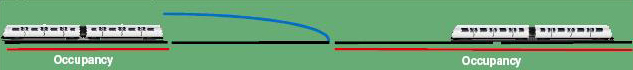
fixed block
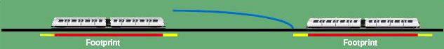
moving block
From the signalling system perspective, the first figure shows the total occupancy of the leading train by including the whole blocks which the train is located on. This is due to the fact that it is impossible for the system to know exactly where the train actually is within these blocks. Therefore, the fixed block system only allows the following train to move up to the last unoccupied block’s border.
In a moving block system as shown in the second figure, the train position and its braking curve is continuously calculated by the trains, and then communicated via radio to the wayside equipment. Thus, the wayside equipment is able to establish protected areas, each one called Limit of Movement Authority (LMA), up to the nearest obstacle (in the figure the tail of the train in front).
It is important to mention that the occupancy calculated in these systems must include a safety margin for location uncertainty (in yellow in the figure) added to the length of the train. Both of them form what is usually called ‘Footprint’. This safety margin depends on the accuracy of the odometry system in the train.
CBTC systems based on moving block allows the reduction of the safety distance between two consecutive trains. This distance is varying according to the continuous updates of the train location and speed, maintaining the safety requirements. This results in a reduced headway between consecutive trains and an increased transport capacity.
Levels of automation
Modern CBTC systems allow different levels of automation or Grades of Automation, GoA, as defined and classified in the IEC 62290-1. In fact, CBTC is not a synonym for “driverless” or “automated trains” although it is considered as a basic technology for this purpose.
The grades of automation available range from a manual protected operation, GoA 1 (usually applied as a fallback operation mode) to the fully automated operation, GoA 4 (Unattended Train Operation, UTO). Intermediate operation modes comprise semi-automated GoA 2 (Semi-automated Operation Mode, STO) or driverless GoA 3 (Driverless Train Operation, DTO). The latter operates without a driver in the cabin, but requires an attendant to face degraded modes of operation as well as guide the passengers in the case of emergencies. The higher the GoA, the higher the safety, functionality and performance levels must be.
Main advantages of the Communications-Based Train Control System:
- Optimized train speeds to gain best line capacity, reduced costs and provide best passenger comfort;
- Guaranteed short term of system delivery and launching;
- Putting in operation from day one;
- Automated operations and easy maintenance;
- Driverless system (or upgradable to driverless) to reduce operating costs;
- Power saving;
- Easy maintenance;
- Easy expansion;
- Easy integration;
- Best immunity against interference;
- Obsolescence-proof;
- 100% safe;
- Minimum trackside equipment.
Innovative solution simplifies the complex route setting and interlocking functions, completely merging them into CBTC:
- Optimum train-centric architecture, with more on-board intelligence and direct train-to-train communication, leading to 20% less equipment and better performances;
- Higher transport capacity with minimal headway (down to 60 seconds);
- Higher operational availability (24 hours) with extreme flexibility of train movements;
- Optimal investment and LCC for all types of line configuration.
- CBTC can be easily integrated with all automation systems for railway transport.
Architecture
The typical architecture of a modern CBTC system comprises the following main subsystems:
Wayside equipment, which includes the interlocking and the subsystems controlling every zone in the line or network (typically containing the wayside ATP and ATO functionalities). Depending on the suppliers, the architectures may be centralized or distributed. The control of the system is performed from a central command ATS, though local control subsystems may be also included as a fallback.
CBTC onboard equipment, including ATP and ATO subsystems in the vehicles.
Train to wayside communication subsystem, currently based on radio links.
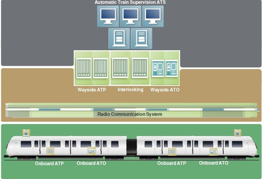
Thus, although a CBTC architecture is always depending on the supplier and its technical approach, the following logical components may be found generally in a typical CBTC architecture:
Onboard ATP system. This subsystem is in charge of the continuous control of the train speed according to the safety profile, and applying the brake if it is necessary. It is also in charge of the communication with the wayside ATP subsystem in order to exchange the information needed for a safe operation (sending speed and braking distance, and receiving the limit of movement authority for a safe operation).
Onboard ATO system. It is responsible for the automatic control of the traction and braking effort in order to keep the train under the threshold established by the ATP subsystem. Its main task is either to facilitate the driver or attendant functions, or even to operate the train in a fully automatic mode while maintaining the traffic regulation targets and passenger comfort. It also allows the selection of different automatic driving strategies to adapt the runtime or even reduce the power consumption.
Wayside ATP system. This subsystem undertakes the management of all the communications with the trains in its area. Additionally, it calculates the limits of movement authority that every train must respect while operating in the mentioned area. This task is therefore critical for the operation safety.
Wayside ATO system. It is in charge of controlling the destination and regulation targets of every train. The wayside ATO functionality provides all the trains in the system with their destination as well as with other data such as the dwell time in the stations. Additionally, it may also perform auxiliary and non-safety related tasks including for instance alarm/event communication and management, or handling skip/hold station commands.
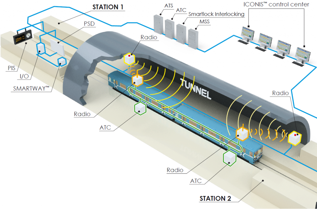
Communication system. The CBTC systems integrate a digital networked radio system by means of antennas or leaky feeder cable for the bi-directional communication between the track equipment and the trains. The 2,4GHz band is commonly used in these systems (same as WiFi), though other alternative frequencies such as 900 MHz (US), 5.8 GHz or other licensed bands may be used as well.
ATS system. The ATS system is commonly integrated within most of the CBTC solutions. Its main task is to act as the interface between the operator and the system, managing the traffic according to the specific regulation criteria. Other tasks may include the event and alarm management as well as acting as the interface with external systems.
Interlocking system. When needed as an independent subsystem (for instance as a fallback system), it will be in charge of the vital control of the trackside objects such as switches or signals, as well as other related functionality. In the case of simpler networks or lines, the functionality of the interlocking may be integrated into the wayside ATP system.
Videos
Sources: wikipedia.com, lotgroup.eu