
Braking Systems
Braking Mechanisms
When a braking force is applied to stop the cars, the force must be transmitted to something other than the cars, for example, to the rails. The braking force can be transmitted either through adhesion, which makes use of friction at the point where the wheels touch the rails, or through ways that do not involve adhesion. Most rolling stock currently uses adhesion braking methods.
Non-adhesion methods do not use friction at the point where the wheels touch the rails and include mounting panels on cars to increase air resistance, or the direct application of pressure from the car to the rail, using shoes. This latter technique involves a device called a rail brake. Most rolling stock braking systems use either electrical brakes, or mechanical brakes.
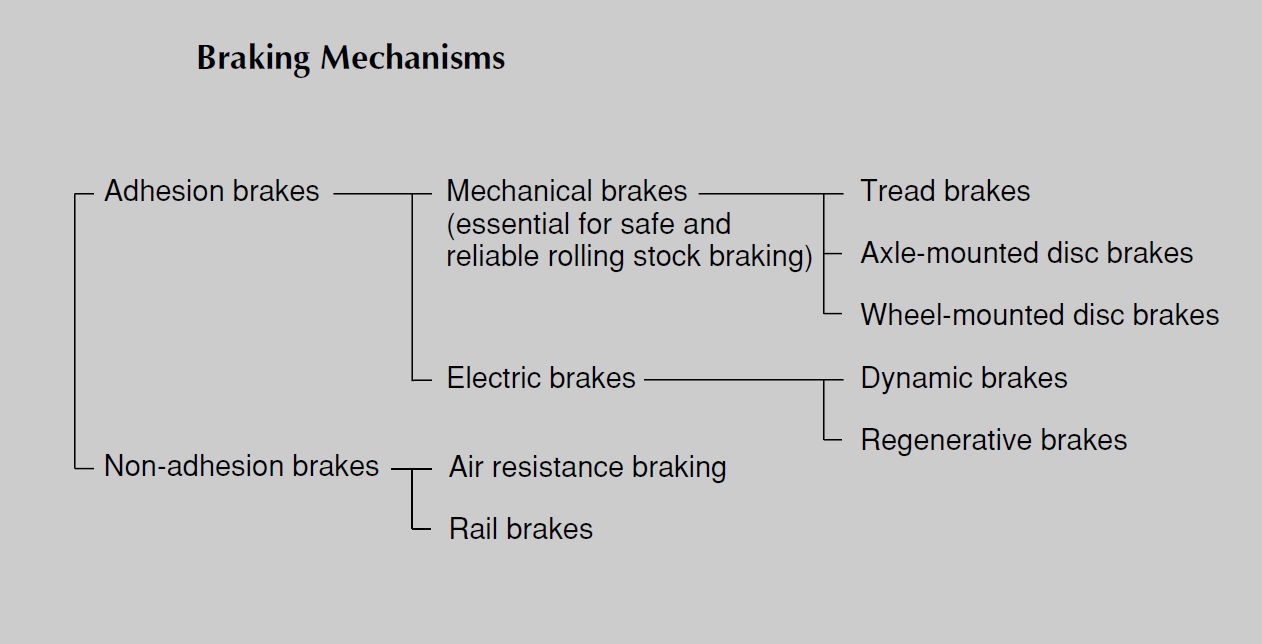
A. Mechanical Braking Systems
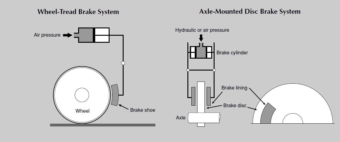
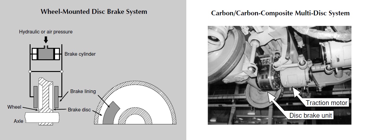
The basic braking devices used by mechanical braking systems are: wheel-tread brakes, axle-mounted disc brakes, and wheel-mounted disc brakes. All these mechanisms use an object (a brake shoe or lining) that applies friction to the disc. The applied pressure is adjusted to control the braking force. In the wheel-tread brake, the brake shoe applies friction to the wheel tread, creating a sliding effect. High-speed trains cannot use this type of brake, since doing so would damage the wheel tread. Instead, they use axle- or wheel-mounted disc brakes. Axle-mounted disc brakes are used on trailer bogies, because they have sufficient space to accommodate such a system. Wheel-mounted disc brakes are used on motor bogies that must accommodate the traction motor and have insufficient space for an axle-mounted brake. In both systems, compressed air or oil is applied to a brake cylinder that forces the brake lining against the disc.
Brake discs are dead weight that are useful only during braking, so operators are keen to install lighter discs. Carbon/carbon-composite multi-discs and aluminium composite discs offer lighter weights and are viewed with considerable interest.
The carbon/carbon-composite multi-disc has alternate sections of carbon-fiber rotors and stators. During braking, they rub against each other to create a frictional force that slows down the wheel or axle. The disc is lighter than conventional materials and has excellent heat-resistant properties.
Aluminium-composite brake discs can be made much lighter than today’s forged steel and cast-iron brake discs. In addition, their structure is the same for both axle- or wheel-mounted discs, achieving a much lighter disc without design changes.
B. Electric Brake Systems
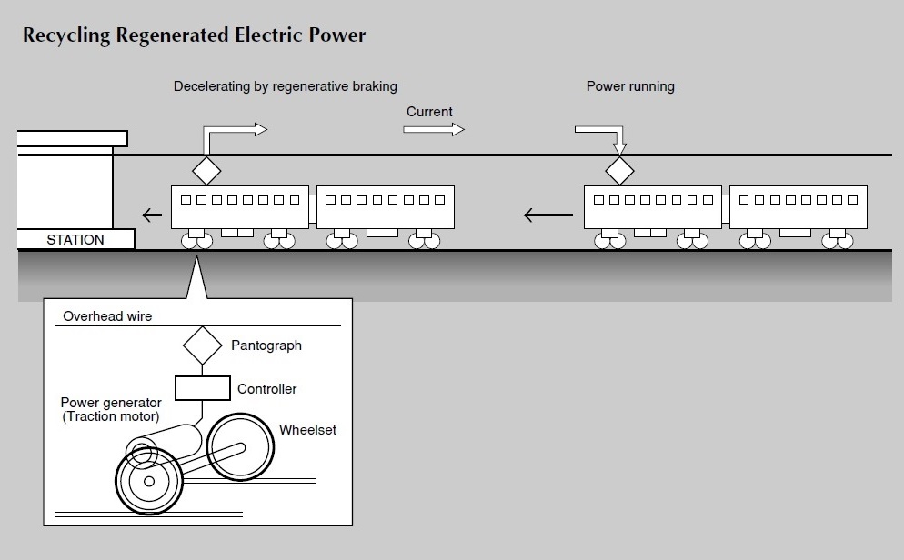
Another braking system used by electric trains is electrical dynamic braking that converts the motor into a braking generator dissipating the kinetic energy as heat. Regenerative braking uses the generated electricity instead of dissipating it as heat, and is becoming more common due to its ability to save energy.
Followin figure shows the principles of the electrical traction, dynamic braking and regenerative braking systems. Although the traction motor drives and accelerates the train, during braking, it acts as an electric generator instead,forming part of a circuit that consists of a main resistor (rheostat), armatures and a field system. Electricity flows through the circuit and is consumed by the main resistor, which converts the kinetic energy of the train into heat and thereby acts as a brake.
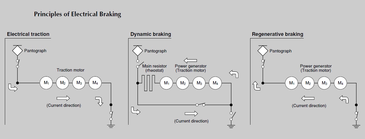
Regenerative braking uses the same type of circuit, but the electricity generated by braking is not consumed by the main resistor. Instead, it is transmitted to the overhead wire. The flow of this electricity is controlled by a controller under the pantograph that opens and closes with split-second timing.
Electrical brake systems are economical because they do not use friction elements, unlike mechanical brake systems. The regenerative braking system is even more economical because the electricity regenerated from the train’s kinetic energy is transmitted to the overhead wire, and becomes available to power other rolling stock. The problem with electrical brake systems is that they occasionally malfunction because they have complex circuits. For this reason they cannot be used as emergency brakes.
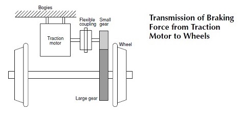
In an electrical braking system, the braking force of the traction motor (generator) is transmitted to the wheels via gears. The generated electricity is adjusted to control braking force.
Braking Command
Brakes must function on every car at the same moment and at the exact required force. The timing and the braking force are controlled by an electrical command system or an air command system.
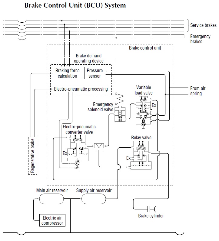
Following figures show a digital electric command system, an air pressure command line, and the systems in a brake control unit (BCU) system, respectively. The digital electric command system controls braking force by applying digital voltage through wires running the full length of the train. The air command system, otherwise known as an analog dispatcher system, controls the air pressure in pipes that also run the full length of the train. The air command system is used in freight wagons and some passenger cars, and can transmit braking commands in rolling stock with no power supply. The electric command system is used in shinkansen and other new trains, and offers lighter weight and better response times, even in long trains. The BCU system keeps the braking force at the optimum level by adjusting it in accordance with braking commands, electrical braking force (regenerative braking), number of passengers, and speed, etc.
Source: ejrcf.or.jp; Railway Technology Today 7 – Braking Systems – Izumi Hasegawa and Seigo Uchida